

Instrument Panel
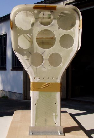
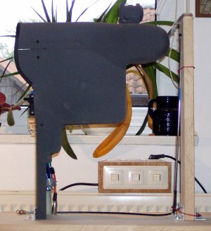
The idea behind building a new instrument panel can be found here. Thats how the glas-fiber construction looks like from the front ...
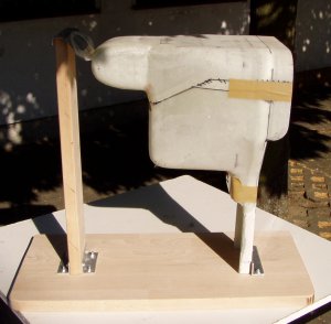
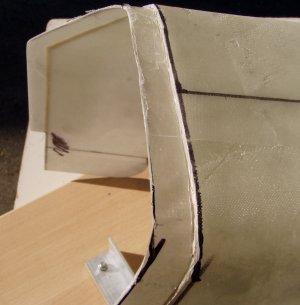
... from the side ...
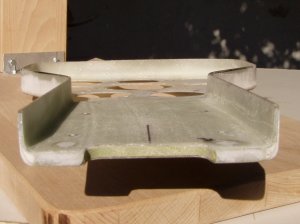
and the separate parts: the upper cover.
Nice to see: the moulded recess, which connects the panel with the ventilation outlet in front of the cockpit. This recess will fail in the case of a crash and the complete instrument panel will submerge under the front canopy frame.
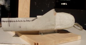
The overlapping part to bold together the upper and lower part of the instrument panel cover.
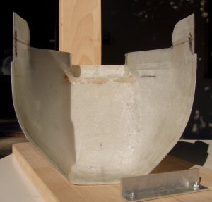
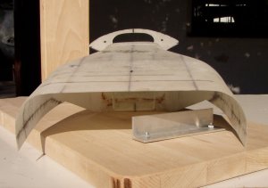
The lower cover from above ...
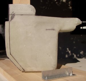
... and from the side-view.
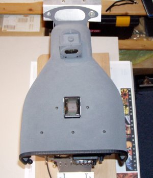
The rather instrument panel including a stiffened lower part - the green foam the picture.
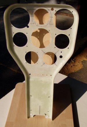
The instrument panel from below.
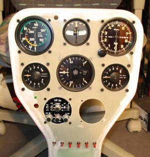
First test installation of the instruments - fits mostly, but the variometer (VP2c) has to swap its position with the bank-and-turn indicator because of its depth.
After finishing the surface with "Nextel" - a really cool stuff! The GSP-antenna is used for my PDA ... a Sharp Zaurus with Linux (what else!) and Cumulus used as software.
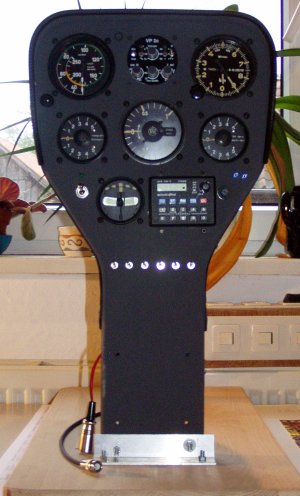
Finalised - Status before the VP2c fails.
From the side-view: the depth of the cover is specially fitted to the depth of the instruments ...
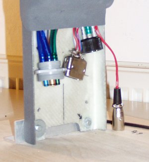
To save the electrical components to over winter in the plane and therefore corrode because of the moist, there is one central connector for all electrical and two connectors for all pneumatic connections between the panel and the rest of the plane. Based on this the complete panel can be removed from the plane within 5 minutes and then over winter in the living room. And: working on the electrical components is really eased ...
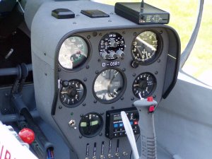
The instrument panel build in.